Tuesday
Fuel pump relay
Fuel pump relays can cause intermittent problems such as hard starting and power loss. The first check is to listen each time you turn the ignition key, you should always hear the electric fuel pump run (a whirling noise) for a few seconds as the pump pressurizes the fuel system. After the fuel pump pressurizes the system, it shuts off. If sometimes you do not hear it and have a hard or no start problem check the fuel pump relay as described below.
 See what pin type you have. Generally 4 or 5 pins.
If four pins, remove relay and bench test as follows:
Using an ohm meter, check between pins 85 and 86. If reading is more or less than 85 ohms replace the unit.
 If five pin type, remove relay and bench test as follows:
Using an ohm meter, check between pins 85 and 86. If reading is more than 120 or less than 40 ohms replace the unit. Check between pins 85 and pins 30 and 87, if less than 10,000 ohms replace the unit.
 If the relay shows burning or distortion from heat, replace the unit and check the plug for damage. If the relay checks good, proceed to a fuel pressure and volume test.
These relays are not expense and are handy for many applications as they have a good amp rating.

If four pins, remove relay and bench test as follows:
Using an ohm meter, check between pins 85 and 86. If reading is more or less than 85 ohms replace the unit.

Using an ohm meter, check between pins 85 and 86. If reading is more than 120 or less than 40 ohms replace the unit. Check between pins 85 and pins 30 and 87, if less than 10,000 ohms replace the unit.

These relays are not expense and are handy for many applications as they have a good amp rating.
Friday
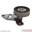
Tension and Idler pulley
My truck with it's 2.3L engine has riveted or pressed on pulleys. They don't unbolt from the flange. The original Ford part numbers were: E97A-3F671-AA and F07A-8675-AA. I was able to find an aftermarket replacement part for them.
For E97A-3F671-AA:
http://www.rockauto.com/dbphp/x,catalog,335,partnum,36155,d,acdelco_36155.html
Pulley info: (82mm x 17mm x 31mm) - Flanged, W/10mm Bushing
This is also Napa #31655

For F07A-8675-AA (MOTORCRAFT A/C DRIVE BELT IDLER PULLEY 1990-1997 Ranger)
Alternate/OEM Part Number(s): F07A8675AA, FOTZ8678D
New Motorcraft # YS196
Napa also carries the other pulley. Gates #36153, Goodyear #49120
http://www.rockauto.com/catalog/moreinfo.php?pk=1145581
Pulley size is 90mm x N/A x 26mm

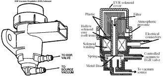
EGR control solenoid

This is a normally closed solenoid that when energized by the ECA (electronic control assemble) it causes a vacuum to flow to the EGR valve. When it is deenergized the vacuum is stopped and the EGR valve is closed.
TESTING THE EGR SOLENOID
The resistance of each solenoid should be 68-78 ohms. If not replace the solenoid. It should flow air (vacuum) when energized. They are expected to have some small leakage when energized or not. This is normal and acceptable.
PCV Valve

TESTING THE PCV VALVE
1. Remove the pcv valve from the rubber hose.
2. Shake it.
3. If it rattles freely it is good, if not or in doubt replace it. If there is a lot of "crud" in the valve, you may need to check the hose to make sure it is not plugged up with debris. If the hose is damaged or brittle, replace it
4. It's a good idea to paint the hose red or white or put some color of electrical tape on the hose to ease finding it next time.
Checking your EGR valve
TESTING YOUR EGR VALVE
 1. Make certain that all vacuum hoses or correctly routed and securely attached. Replace cut, cracked, crimped, melted/burnt or broken hoses.
2. Make certain there's no vacuum to the EGR valve at idle with the engine at normal operating temperature.
3. Install a tachometer.
4. Disconnected the idle bypass valve electrical connector.
5. Remove the vacuum supply hose from the EGR valve nipple and plug the hose.
6. With the transmission in neutral, start the engine and observe the engine idle speed, if necessary, adjust the idle speed to the emission decal specifications.
7. Using a hand vac pump, slowly pump up like 5 to 10 inches of mercury vacuum to the EGR valve vacuum nipple.
8. If any of the following occur replace the valve: engine does not stall; idle speed does not drop more than 100 rpm; idle speed does not return to normal plus or minus 25 rpm after the vacuum is removed.
9. Reconnect the idle bypass valve electrical connector. Unplug and reconnect the EGR valve vacuum supply hose.
There are two types of position sensors for the EGR valve. This also determines the correct EGR name, either PFE or DPFE (see below). Look at the sensor that is mounted to the EGR valve itself. Physically, the PFE sensor has one pressure input nipple. The DPFE sensor has two pressure input nipples. Electrically, both the PFE and the DPFE sensors are three wire sensors. Each have a 5-volt reference from the ECM, a ground, and a sensor output. It is in the sensor output voltage where these two sensors differ.
The EVP came in two versions: one black and the other white (off gray). These units have different values even though they mount and look the same. Make sure you have the right one.
Monday
Ranger Coil Pack
Original part # E9TF-12029-AA
FD487 - Standard Motor 5C1117 - AIRTEX / WELLS |
|---|
This same coil is also found on a Mazda 626.
Also on these vehicles:
FORD TRUCK 89-99
LINCOLN 91-97
MAZDA 94-97
FORD MERCURY 91-99


If your looking for some extra kick, try the MSN coil packs #PN-8241 listed for 95-04 Fords (Mustangs).
Coil Pack Trace
Tech Note 014:
 The DIS module in this system uses four power transistors one for each primary winding. Figure #1 testing primary current with low amp prob. The right side coil pack in this system is responsible for firing the air/fuel mixture that makes the power. Red trace, #1 primary winding. Blue trace, #2 primary winding. Both winding and power transistors are good in this coil pack. The primary windings are pulling 5.2 amps probe conversion is 100mv=1amp.
 Figure #2 left side coil pack. This side is responsible for emissions reduction. Blue trace, #1 primary winding shows high resistance problem leading edge. Trailing edge looks normal. Red trace, #2 primary winding leading edge looks normal trailing edge is the one with the problem. I suspect that the transistor is partially shorted. The NPN transistor completes the circuit by grounding the primary winding and charging the coil. As the coil charges the magnetic field builds, the transistor then opens the circuit, the field collapses rapidly, and induces the high voltage in the secondary winding plug fires. Looking at the trailing edge you can see a glitch and a sloping down to zero amps. This glitch is setting trouble code #18 in memory erratic input to ECA. This code in memory on dual plug systems puts the ECA into FMEM or limp in mode.
DUAL PLUG IGNITION: 1991 Ford Ranger 2.3L EFI
Comparison primary current waveforms of the left and right side coil packs.
Comparison primary current waveforms of the left and right side coil packs.
 The DIS module in this system uses four power transistors one for each primary winding. Figure #1 testing primary current with low amp prob. The right side coil pack in this system is responsible for firing the air/fuel mixture that makes the power. Red trace, #1 primary winding. Blue trace, #2 primary winding. Both winding and power transistors are good in this coil pack. The primary windings are pulling 5.2 amps probe conversion is 100mv=1amp.
 Figure #2 left side coil pack. This side is responsible for emissions reduction. Blue trace, #1 primary winding shows high resistance problem leading edge. Trailing edge looks normal. Red trace, #2 primary winding leading edge looks normal trailing edge is the one with the problem. I suspect that the transistor is partially shorted. The NPN transistor completes the circuit by grounding the primary winding and charging the coil. As the coil charges the magnetic field builds, the transistor then opens the circuit, the field collapses rapidly, and induces the high voltage in the secondary winding plug fires. Looking at the trailing edge you can see a glitch and a sloping down to zero amps. This glitch is setting trouble code #18 in memory erratic input to ECA. This code in memory on dual plug systems puts the ECA into FMEM or limp in mode.
Sunday
Service books
I use this Haynes manual. It is not bad, but the pictures are of general quality and the index is of medium quality. You can buy it online or at most auto stores.


2.3L timing belt replacement or check
Here is the complete procedure to replace or check your Ford 2.3 Liter timing belt with some helpful tips on the job. Removing the timing cover and replacement of the timing belt is a straight forward job that can be easily handled. To learn when you should replace the timing belt go HERE. Follow the service steps below and it will be easy and save you money and time.
Removal
1. TIP: If your engine has a lot of grease and dirt on it, now would be a good time BEFORE you start, to clean it. It is not necessary, but will make the job easier, cleaner and much easier to check for damage, leaks and/or bad parts.
2. Check for any trouble codes and then disconnect the negative battery cable. Rotate engine clockwise and position cylinder No. 1 on TDC (Top Dead Center) of compression stroke. Ensure "I" mark on the crankshaft pulley aligns with TDC mark on outer timing belt cover.
3. Remove the rubber inspection plug in timing cover (at camshaft level). Looking through the rubber plug hole of outer timing belt cover, ensure camshaft sprocket timing mark (triangle shaped) aligns with the inner pointer. If you do not see the timing mark on the camshaft pulley at all, you maybe on the wrong stroke, rotate crank another 360 degrees and check again. See Fig. 1. (If timing has "jumped" this will not line up perfectly, just leave it for now and keep crank on TDC)
4. TIP: If this is your first time to do this type of work, snap a few pictures on your cell phone or camera of what you are about to take apart. Take them from several angles. Use labeled plastic bags for small parts or screw bolts back into the hole from where they came.
5. It is not necessary to remove the fan shroud or upper radiator hose, but, it will make the job easier if you do. You may need to remove the radiator if your balancer puller has a long screw. Before loosening or removing the belts, break the cooling fans nuts loose, but do not remove (you will thank me later).
6. Loosen the drive belt belt tensioner. Remove drive belts and check condition (mark them for their location). Remove cooling fan, fan clutch and pulley (the fan and clutch can be removed as one assembly). Check cooling fan for cracks and damage. Drain cooling system. Remove the belt tensioners (NOTE! one bolt may have pipe dope on it when reinserted) and check that the tensioner pulleys operate freely and do not growl or feel "rough" when spun, if they do or are damaged replace them.
7. Check again that timing is still at TDC. Remove timing cover. It "snaps" on. Use a screwdriver to unsnap the locks. Do yourself a favor and snap a picture(s) now! Put the rubber plug back in timing cover before you lose it.
8. Inspect the water pump while you have all this apart. If it is leaking or the shaft has up and down movement you might want to replace it while you have this apart. Check that lower radiator hose and where the heater hoses attach to the water pump, if they are swollen replace them.
9. Remove harmonic balancer (crankshaft pulley) retaining bolt. TRICK: While the bolt is out, use a small drill and drill a dimple in the center of the head of the crankshaft bolt. This "dimple" will allow you to keep your balancer pulley tip centered on the bolt and stop it from moving around as you use it. You will need to also remove two bolts on the crankshaft pulley in order to attach your balancer puller bolts (thread them in well). Reinsert (screw) your crankshaft bolt in about 1/2 way, attach your puller and start removing the pulley, as you near the end of travel, stop, remove the puller, unscrew more of the crankshaft bolt and repeat until you have the pulley off. Remove crankshaft pulley. Take another picture.
10. Loosen timing belt tensioner bolts. DON'T TAKE THE BOLTS OUT. Using Camshaft Belt Tensioner (T74P-6254-A) or equivalent (a bar clamp works great), release spring tension on belt tensioner (Rotating belt tensioner away from timing belt), then tighten the adjusting bolt to hold tensioner in the released position.
11. Removing timing belt:
You will note that the timing belt is trapped behind a large washer on the crankshaft and the washer is trapped by the crankshaft position sensor. Do not remove or loosen the sensor. By simply cocking the washer some and pulling it slightly forward, the belt will slip out with a light pull. Remove the belt. Spin the timing belt tensioner by hand and check condition and/or replace unit. Take some time and clean the area where the new belt will go.
12. If the crankshaft seal is leaking, now is your chance to replace it.
13. Verify that all pulleys (gears) are pointing to their indexing marks.
14. Install new timing belt. Slowly, release the tensioner upon the belt. Do not tighten the bolts yet. The tensioner must be able to move to take up the slack in the next step. TIP: Write the date and mileage of the replacement with "white out" on the timing cover for a record.
15. DON'T SKIP THIS STEP.
After replacing the timing belt and applying the tensioner in step 14, rotate the crankshaft clockwise by hand (screw in crankshaft bolt and use wrench or socket) 2 full BELT revolutions, stop at TDC and check the timing marks again. Check that all pulleys align to their proper indexing marks. If all is good, tighten the tensioner bolts. (after rotating, it has taken all the slop out of the belt). Lightly grease the crankshaft shaft and lube the inside mating surface of the crankshaft pulley. Very lightly grease the crankshaft seal lip if it was replaced. Grease the washer base of the crankshaft bolt (this helps to get the proper torque). Install the balancer using the crankshaft bolt to "press" it on (reverse of step 9 above). Torque to specs. I used 120 ft/lbs. Button it all back up. If you are replacing the water pump, remember to screw the fan studs in before you install it.
16. Refill the cooling system. Make sure all the hoses, tubes and connectors are reattached, start engine. After about 15 seconds, turn it off. Recheck the timing. Turn the engine by hand till the crank is at TDC. Remove the inspection rubber plug and verify that the timing mark on the camshaft sprocket is at the pointer, if it is, congratulations you got the belt on correct, if you do not see it at all, rotate the crank another 180 degrees and recheck, if you see the timing mark but it does not line up, you may be a tooth off and you will have to reinstall the belt.
17. If all is good, start engine and run till the thermostat opens. Top off the cooling system. The engine may sound rough as the computer will need to "learn" all over again. This should settle down. Check for leaks.


Before starting a 2.3 liter timing belt replacement, you might want to consider replacing the following parts also as you will access to them during this replacement: Radiator hoses, heater hoses, water pump, thermostat, crankshaft seal, timing belt tensioner, radiator or radiator flush, tensioners, fan blade, fan clutch, drive belts. Many of these parts can be ordered online in advance at a great savings. This is also a good time to check (or at least look at) the drivers side coil pack. This coil pack is buried in the engine and is subject to heavy deterioration and a bitch to get to later. When in doubt, replace it.
The biggest tip I can give you is to first read all the steps and look at the diagrams below below before you start. If you charge head first, you will make more work for yourself and this may require you to buy special tools.
Removal
1. TIP: If your engine has a lot of grease and dirt on it, now would be a good time BEFORE you start, to clean it. It is not necessary, but will make the job easier, cleaner and much easier to check for damage, leaks and/or bad parts.
2. Check for any trouble codes and then disconnect the negative battery cable. Rotate engine clockwise and position cylinder No. 1 on TDC (Top Dead Center) of compression stroke. Ensure "I" mark on the crankshaft pulley aligns with TDC mark on outer timing belt cover.
3. Remove the rubber inspection plug in timing cover (at camshaft level). Looking through the rubber plug hole of outer timing belt cover, ensure camshaft sprocket timing mark (triangle shaped) aligns with the inner pointer. If you do not see the timing mark on the camshaft pulley at all, you maybe on the wrong stroke, rotate crank another 360 degrees and check again. See Fig. 1. (If timing has "jumped" this will not line up perfectly, just leave it for now and keep crank on TDC)
4. TIP: If this is your first time to do this type of work, snap a few pictures on your cell phone or camera of what you are about to take apart. Take them from several angles. Use labeled plastic bags for small parts or screw bolts back into the hole from where they came.
5. It is not necessary to remove the fan shroud or upper radiator hose, but, it will make the job easier if you do. You may need to remove the radiator if your balancer puller has a long screw. Before loosening or removing the belts, break the cooling fans nuts loose, but do not remove (you will thank me later).
6. Loosen the drive belt belt tensioner. Remove drive belts and check condition (mark them for their location). Remove cooling fan, fan clutch and pulley (the fan and clutch can be removed as one assembly). Check cooling fan for cracks and damage. Drain cooling system. Remove the belt tensioners (NOTE! one bolt may have pipe dope on it when reinserted) and check that the tensioner pulleys operate freely and do not growl or feel "rough" when spun, if they do or are damaged replace them.
7. Check again that timing is still at TDC. Remove timing cover. It "snaps" on. Use a screwdriver to unsnap the locks. Do yourself a favor and snap a picture(s) now! Put the rubber plug back in timing cover before you lose it.
8. Inspect the water pump while you have all this apart. If it is leaking or the shaft has up and down movement you might want to replace it while you have this apart. Check that lower radiator hose and where the heater hoses attach to the water pump, if they are swollen replace them.
9. Remove harmonic balancer (crankshaft pulley) retaining bolt. TRICK: While the bolt is out, use a small drill and drill a dimple in the center of the head of the crankshaft bolt. This "dimple" will allow you to keep your balancer pulley tip centered on the bolt and stop it from moving around as you use it. You will need to also remove two bolts on the crankshaft pulley in order to attach your balancer puller bolts (thread them in well). Reinsert (screw) your crankshaft bolt in about 1/2 way, attach your puller and start removing the pulley, as you near the end of travel, stop, remove the puller, unscrew more of the crankshaft bolt and repeat until you have the pulley off. Remove crankshaft pulley. Take another picture.
10. Loosen timing belt tensioner bolts. DON'T TAKE THE BOLTS OUT. Using Camshaft Belt Tensioner (T74P-6254-A) or equivalent (a bar clamp works great), release spring tension on belt tensioner (Rotating belt tensioner away from timing belt), then tighten the adjusting bolt to hold tensioner in the released position.
11. Removing timing belt:
You will note that the timing belt is trapped behind a large washer on the crankshaft and the washer is trapped by the crankshaft position sensor. Do not remove or loosen the sensor. By simply cocking the washer some and pulling it slightly forward, the belt will slip out with a light pull. Remove the belt. Spin the timing belt tensioner by hand and check condition and/or replace unit. Take some time and clean the area where the new belt will go.
12. If the crankshaft seal is leaking, now is your chance to replace it.
13. Verify that all pulleys (gears) are pointing to their indexing marks.
14. Install new timing belt. Slowly, release the tensioner upon the belt. Do not tighten the bolts yet. The tensioner must be able to move to take up the slack in the next step. TIP: Write the date and mileage of the replacement with "white out" on the timing cover for a record.
15. DON'T SKIP THIS STEP.
After replacing the timing belt and applying the tensioner in step 14, rotate the crankshaft clockwise by hand (screw in crankshaft bolt and use wrench or socket) 2 full BELT revolutions, stop at TDC and check the timing marks again. Check that all pulleys align to their proper indexing marks. If all is good, tighten the tensioner bolts. (after rotating, it has taken all the slop out of the belt). Lightly grease the crankshaft shaft and lube the inside mating surface of the crankshaft pulley. Very lightly grease the crankshaft seal lip if it was replaced. Grease the washer base of the crankshaft bolt (this helps to get the proper torque). Install the balancer using the crankshaft bolt to "press" it on (reverse of step 9 above). Torque to specs. I used 120 ft/lbs. Button it all back up. If you are replacing the water pump, remember to screw the fan studs in before you install it.
16. Refill the cooling system. Make sure all the hoses, tubes and connectors are reattached, start engine. After about 15 seconds, turn it off. Recheck the timing. Turn the engine by hand till the crank is at TDC. Remove the inspection rubber plug and verify that the timing mark on the camshaft sprocket is at the pointer, if it is, congratulations you got the belt on correct, if you do not see it at all, rotate the crank another 180 degrees and recheck, if you see the timing mark but it does not line up, you may be a tooth off and you will have to reinstall the belt.
17. If all is good, start engine and run till the thermostat opens. Top off the cooling system. The engine may sound rough as the computer will need to "learn" all over again. This should settle down. Check for leaks.


Subscribe to:
Posts (Atom)