Thursday

2.3L engine pics

Often in the repair manuals their pictures would either suck or just never seem to show the one part, wiring, or location I needed to see.  So here is a few that might help you.
Cleaned intake

Old ignition module


Crank sensor


 Test plug sprout


Lower coil mount


Spring detail


Monday

Ignition Control Module R&R - 1991 Ranger

Tips you can use. This control module job can go great or poorly. Mine went poorly.

Outside of the fact that the unit is buried behind the alternator and not wrench friendly, my bolt heads were rusted beyond use.  This would require the removal of the lower intake in order to to attempt the removal of the unit.  Ultimately one bolt would snap, The other two bolts came out heat and oil, but only after breaking the unit off the bolts, so I could use vise grips on the bolts.

TIP1: Heat is the enemy of the ignition control module.
Note there are only three bolts.  The lower two are also grounds (verify the vehicle ground to manifold located at #4 cyl on manifold is good).  Clean the backing plate well before installing a new unit.  Note which plug is UP. Use anti seize compound on the bolts. Use heat compound or di-electric grease under the module required for heat transfer.

TIP2: Use a tap to clean the threads before installing bolts.  If they break off during removal, you may need to remove the manifold.

TIP3: Remove the sensor from the manifold located in the tube to #1 cylinder. This is often choked with crap from the EGR system. Clean with a blast of carb cleaner and reuse.


Sunday

2.3L fuel injector removal and service

These are a type EV-1 style. Go HERE.

Coil Pack Pins

Identify the connector pins on the ignition coil assembly. If you look at the electrical connector you unplugged on the ignition coil assembly, you will see three small pins inside. The one in the center is B+. 


Click image to see an enlarged view
Fig. Fig. 2: Engine ignition coil harness connections-2.3L, 2.5L and 5.0L engines


  • Disconnect the spark plug wires from the ignition coils on the assembly by hand. The wires have a locking tab. To disconnect them squeeze the locking tabs inward at the terminal and twist the boot while pulling up. This also a good time to check the resistance of the spark plug wires and check for damage as you have them apart already.


  • Removing the coil pack and bench testing is best.  Often there is cracking and damage on the underside of the unit which only can be seen if it is removed and cleaned.


  • Get a multimeter (digital is best) and set it to the correct range for ohm testing.


  • Checking the ignition coils' primary resistance. Probe pins B+ and coil 1 of the connector on the ignition coil assembly, and make a note of the number on the multimeter readout. Then probe pins B+ and coil 2.  Make a note of each of your meter readouts. The resistance value for each pair of pins in your three tests should be between 0.3 and 1.0 ohms. If any of the coil packs (2 per unit) test out of this range (over or under), the pack should be replaced.


  • Check the ignition coils secondary resistance. Select the appropriate range in your multimeter so you can read between 6,500 and 11,500 ohms in the ohmmeter scale. Probe the two terminals on coil 1, where the spark plug wires 1 and 4 connect to, and make a note of your multimeter readout number. Probe the terminals on coil 2 and 3 and make a note of the results, as well. Any coil that tests outside of the 6,500 through 11,500 ohms range should be replaced. On 2.3L, 2.5L and 5.0L engines, if one coil pack is found to be defective, the other pack does not need to be replaced.


  • If any pack tested bad in either test, replace the unit.


  • The condenser usually mounted to the coil pack goes bad often creating a ignition miss, replace this item.


  • If the pack is good, reconnect the electrical plug, spark plug wires and the negative battery cable. 


  • Other sensors that effect the timing are: MAP ( Manifold Absolute Pressure sensor ), IAT ( Intake Air Temperature sensor ), ECT ( Engine Coolant Temperature sensor ), EVP ( EGR Valve Position sensor ) and TPS ( Throttle Position Sensor ).
  • Tuesday

    Air Bypass Valve Info and testing

    Ford air bypass valve
    The ford ranger air bypass valve solenoid is used to control engine idle speed and is operated by the EEC-IV control module. This valve allows air to pass around the throttle plates to control:

    1. cold engine fast idle
    2. no touch start
    3. dashpot
    4. over temperature idle boost
    5. engine idle load correction.

    Symptoms of a bad one:
    1. Engine stalling
    2. Surging
    3. Poor idle conditions
    4. "Check engine light" on
    Diagnosis:

    The signal to the solenoid should be 1 volt or less at curb idle, (with all accessory loads off). Applying 12 volts to the solenoid will cause a neutral idle speed change greater than 1000 rpm. Check for shorts between both solenoid terminals and the case.

    Codes 12, 13, 16, 17 & 19 all indicate idle speed is out of spec (too high or too low). Codes 47 and 48 indicate a fuel mixture problem which could be caused by an air leak. It may be possible to clean the ports with electrical safe clearer, do not use regular carb cleaner as it will remove the protective coating. Clean port holes in the manifold also before reinstalling.

    Monday

    Ranger brake proportional valve

    This proportional valve is next to the transmission mounted to the frame, drivers side, toward rear of engine. It will most likely take some heat to get the old line fittings out. You can get a new valve at Rock Auto online.  About $120. Use never seize on the line fittings when you replace it.

    Update: Ranger power loss, bogging, no acceleration

    The catalytic converter was not the only problem. I decided before spending the money for a new cat, I would beat out the inside of the old one first.  A tougher job than you might think.  Took about hour or so and I need a heavy wire hook to remove metal packing and a pipe to break the inside up and a vacuum to suck the inside out also.

    Fuel rail schrader valve
    On the initial test drive, the problem returned and I wound up on the side of a busy highway.  Once again finding no problem, I started back to the basics.  I checked the fuel rail (for gas) using the schrader valve on the rail. The picture is not my truck, but this is what it looks like on the truck. Much to surprise it was full of air and not fuel.

    I have not checked this out fully yet. More later.

    Update:
    Yes, low on gas was this problem.  However, the power loss problem was still not solved. The short answer turned out to be a combination of several problems.
    Clogged sensor
    1. The air sensor in the intake manifold was coated with goo.  Cleaned and reinstalled.
    2. The ignition module was bad.  See detail elsewhere on site.
    3. The inner air passage inside the intake to the EGR valve was blocked/choked. So bad it had no flow. Use a McDonalds straw to probe it on your truck. The straw (5/16) is just the right size, the tunnel is straight.
    4. The ground wire on the intake (needed for the ignition module) was weak. Replaced it.
    5. The intake was very very dirty. Cleaned it.
    6. Decided to replace the injectors with a set from a mustang 4 cly 2.3L. Mine were rusty and needed a cleaning. By the way, they work great.
    7. The blocked cat converter was "cleared" earlier.

    Look at odd shape near center - Egr clogged vent

    Tuesday

    Ford Distributorless Ignition System (DIS)


    Ford DIS System
    The distributorless ignition system (DIS) for the Ford 2.3L twin spark plug engine consists of the following components:
    Crankshaft timing sensor
    DIS module
    Two ignition coil packs
    Spark angle portion of EEC-IV
    Crankshaft Timing Sensor

    The crankshaft timing sensor is a dual hall effect magnetic switch, which is actuated by the dual vane cup on the crankshaft pulley hub assembly. This sensor generates two separate signals, PIP (profile ignition pick-up) and CID (cylinder identification). The PIP signal provides base timing and RPM information, while the CID signal is used to synchronize the ignition coils. Initial timing (base timing) is set at 10 degrees BTDC and is not adjustable. Ignition Coil Packs
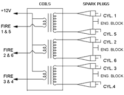
    Two ignition coil packs are used for the 2.3L dual plug engine. The two ignition coil packs are triggered by the DIS module and are timed by the EEC-IV. Each coil pack contains two separate ignition coils for a total of four ignition coils. Each ignition coil fires two spark plugs simultaneously, one spark plug on the compression stroke and one on the exhaust stroke. The spark plug fired on the exhaust stroke uses very little of the ignition coils, stored energy, and the majority of the ignition coils, energy is used by the spark plug on the compression stroke. Since these two spark plugs are connected in series, the firing voltage of one spark plug will be negative with respect to ground, while the other will be positive with respect to ground. Refer to thePowertrain Control/Emissions Diagnosis Manual for additional information on spark plug polarity.

    DIS Module
    The main function of the DIS module is to switch between ignition coils and trigger the coils to spark. The DIS ignition module receives the PIP and CID signals from the crankshaft timing sensor, and the SPOUT (spark out) signal from the EEC-IV module. During normal operation, PIP is passed on to the EEC-IV module and provides base timing and RPM information. The CID signal provides the DIS ignition module with the information required to switch between the coils for cylinders 1 and 4 and the coils for cylinders 2 and 3. The SPOUT signal (from the EEC-IV) contains the optimum spark timing and dwell time information. The dwell time is controlled or varied by varying the duty cycle (duration) of the SPOUT signal. This feature is called CCD (computer controlled dwell). Therefore, with the proper inputs of PIP, CID and SPOUT the DIS ignition module turns the ignition coils on and off in the proper sequence for spark control. CID is also sent to the EEC-IV micro-processor to allow for Bank to Bank fuel control.

    Failure Mode Effects Management
    During some DIS system faults, the Failure Mode Effects Management (FMEM) portion of the DIS ignition module will maintain vehicle operation. If the DIS ignition module does not receive the SPOUT input, it will automatically turn the ignition coils on and off using the PIP signal. However, this will result in fixed spark timing (ten degrees BTDC) and a fixed dwell time (no CCD). If the DIS ignition module does not receive the CID input during engine cranking, random coil synchronization will be attempted by the module. Therefore, several start attempts (cycling the ignition from OFF to START) may be required to start the engine. If the DIS module loses CID input while engine is running, the module will remember the proper firing sequence and continue to fire to maintain engine operation.


    Dual Plug Inhibit

    Dual Plug Inhibit (DPI) is a function of the EEC-IV that is only used when the vehicle is being started at temperatures -7° C (20° F) and below. During engine cranking, the EEC-IV will only fire the spark plugs on the right hand side of the engine. When the engine has started, the EEC-IV will send a signal to the DIS module to start normal dual plug operation.


    Ignition Diagnostic Monitor

    The Ignition Diagnostic Monitor (IDM) is a function of the DIS module. The DIS module sends information on system failures to the EEC-IV which stores the information for diagnostic self test. The IDM signal also is used to drive the vehicle instrument tachometer, and test tachometer for system.

    Testing
    You can find a good DIS testing procedure using a breakout box HERE. The factory pinpoint test mentions using a breakout box (BOB). You can do the same test without a breakout box. The BOB just lets you connect to each wire non-intrusively. Without the BOB, you have to locate each wire and probe directly into the wire. The pinpoint tests refer to overlays and test harnesses, just read over the test first and get an idea what the test is checking, and then you can do the test without using the BOB and associated equipment.


    DIS Break out box

    Engine and Emission Devices

    What are the engine/emission controls most likely found on a 91 Ranger? I personally call any device attached under my hood an engine device, while technically wrong, does it really matter? If they go bad, my engine suffers. Check your emission label under the hood.

    These devices can further be divided into Input (sensor or devices that PROVIDE information, usually to the brain) or output (devices that change some other setting, device or manipulative some linkage or device).

    They are as follows:

    1. The battery.
    2. The ACT (Air Charge Temperature Sensor).
    3. The ECA (Electronic Control Assembly)
    4. The ECT (Engine Coolant Sensor)
    5. The EGR (Exhaust Gas Recirculation Valve)
    6. The EVP (EGR Valve Position Sensor)
    7. The MAP (Manifold Absolute Pressure Sensor)
    8. The EGO (Exhaust Gas Oxygen Sensor)
    9. The TPS (Throttle Position Sensor)
    10. The EEC
    11. The CANP (Canister Purge Soloniod)
    12. The ISC (Idle Speed Control)
    13. The TAB (Thermactor Air By-pass)
    14. The TAD (Thermactor Air Diverter)
    15. The TFI-IV (Ignition control module)
    16. The EEC Power Relay
    17. The A/C and Cooling fan controller module
    18. The EEC-IV (Engine Management System)(the "brain")

    91 Ranger 5 speed Transmission

    Ford Ranger 5 Speed Trans

    Saturday

    2.3L Coolant Sending Unit or Coolant Sensor

    Before going to the trouble of removing the coolant sender from the 2.3L Ford engine block and testing it, perform the tests presented to ensure that it is the sender malfunctioning, and not another part of the circuit.  Unit is on Left side rear of engine, under cylinder head, near oil filter (see the diagrams).

    Steps:
    1. Verify that engine to body grounding strap is good and not corroded.  Bad or missing strap will cause high temp readings.
    2. Check wiring to sensor for damage and corrosion.
    3. Verify full coolant level.
    4. Check sensor: 73 ohms cold, 10 ohms hot. (+/- 2 ohms)

    How to removal and install.
    1. Disconnect the negative battery cable.
    2. Remove the radiator cap to relieve any system pressure.
    3. Disconnect the wiring at the coolant sender.
    4. Remove the coolant temperature sender from the engine.
    5. Coat the threads on the sender with Teflon® tape or electrically conductive sealer, then install the sender. 6. Tighten the sender to 107-143 inch lbs. (12-16 Nm) NOT ft/lbs.
    7. Attach the wiring to the coolant sending unit and connect the negative battery cable.
    8. If necessary, add antifreeze to replace any lost coolant, then install the radiator cap.

    Sensor Pics (could be either)
    2.3 L coolant sensor 
    2.3L coolant sending unit


    You can also check the unit in a pan of water, if removed from the truck.

    Friday

    Ford 2.3L engine Notes

    2.3L I4 SOHC 8V FI Engine

    Check the "years covered" on the parts before buying.

    Cylinder Head
    PartYears CoveredPart Number
    Head Bolts83-01ES72137 (FP)
    Exhaust Valve (1.500” head, .3414” stem dia, 4.792” OAL)83-94V3943
    Exhaust Valve (1.500” head, .2740” stem dia, 4.8070” OAL)95-01V4553
    Intake Valve (1.735” head, .3419” stem dia, 4.787” OAL)83-94V2170
    Intake Valve (1.735” head, .2750” stem dia, 4.787” OAL)95-01V4488
    Valve Guide (.3440 ID, 2.1880” OAL-spiral reamed & flg)83-94VG1372
    Valve Guide (Threaded, .2765” ID, 1.9300” OAL)95-97VG1389T
    Valve Spring (1.9800” free height w/ damper)83-94VS1459
    Valve Spring (2.0197” free height)95-01VS1647
    Valve Keeper/Lock83-94VK205
    Valve Keeper/Lock (Hard)83-94VK205R
    Valve Keeper/Lock95-01VK287
    Valve Spring Insert [(shims) (A=.060” B=.030” C=.015”)83-94259-102A or B or C
    Engine
    PartYears CoveredPart Number
    Connecting Rods (Forging #D42E-AA)1974 - 1997R25BJ (FM)
    Pistons - 2.3L (2-2.00mm/1-4.76mm rings, Comp Dist:1.578”. Pin Dia: .9122”
    8.7:1 Comp Ratio, Flat Head- w/2 Valve Reliefs)
    1977 - 1991H435P
    Pistons - 2.3L (2-1.5mm/1-4.00mm rings, Comp Dist: 1.575”, Pin Dia: .9122”
    Flat Head- w/2 Valve Reliefs)
    1983 - 1994H537P
    Pistons - 2.3L (2-1.5mm/1-4.00mm rings, Comp Dist: 1.578”, Pin Dia: .9122”
    8.7:1 Comp Ratio, Flat Head- w/2 Valve Reliefs)
    1982 - 1989495P
    Pistons - 2.3? (2-1.5mm/1-3.00mm rings, Comp Dist: 1.335”, Pin Dia: .9122”
    Flat Head- w/2 Valve Reliefs)
    1995 - 1997H676P
    Oil Pump (4/8/85 and older) (Not For Use w/ Cast Aluminum Oil Pan)1980 - 1985224-41160
    Oil Pump High Volume (Not For Use w/ Cast Aluminum Oil Pan)1980 - 1995224-41160V
    Oil Pump (4/9/85 and newer)1986 - 1994224-41127
    Oil Pump Shaft1980 - 1994224-61160
    Oil pump screen1977 - 1985224-12160
    Oil pump screen1986 - 1994224-13160