The Ignition Module is tasked with activating the two Ignition Coil Packs that feed the 8 Spark Plugs that the 2.3L 4 Cylinder Engine is equipped with.
Full procedure
Here's the basics that you need to get to the bottom of the problem. In a nutshell, this is what happens when you turn On the Key and crank the Engine:
The Crank Sensor is fed with Power and Ground.
The Crank Sensor is a Hall-Effect type Sensor.
The Crankshaft rotation induces the Crank Sensor to start creating two separate Crank Signals.
One Crank Signal is called the CKP (Crankshaft Position) Signal.
The CKP Signal is only sent to the ICM.
The other Crank Signal is called the CDI (Cylinder Identification) Signal.
The CID (Cylinder Identification) Signal is the one that helps the Ignition Control Module synchronize the Ignition Coil Packs so that they fire in the correct Firing Order.
Both the ICM and the PCM receive the CID Signal.
The Ignition Module now starts to activate the Coil Packs.
During Engine Cranking, only the Right Side Spark Plugs (Exhaust Manifold Side of the Engine) are fired.
Once the Engine starts, the PCM now commands the ICM to fire both Coil Packs through the Dual Plug Inhibit (DPI) circuit (circuit 6 of the ICM Top Connector), .
Each Coil Pack feeds Spark to 4 Spark Plugs on either side of the Engine.
Spark Plugs on the Intake Manifold Side of the Engine are referred to as: Intake Side Spark Plugs or Right Side Spark Plugs.
Spark Plugs on the Exhaust Manifold Side of the Engine are referred to as: Exhaust Side Spark Plugs or Left Side Spark Plugs.
Sunday

1991 2WD Ranger and F150 ball joint replacement steps
 Time for some new ball joints and suspension parts. The Ranger starting pitching when I drove over uneven payments or lines in the payment. An inspection reveled one bad upper ball joint. Since all the other parts have to come off and I don't as a rule reuse a part once I have taken it off, new parts are in order.
Ball joints:
REMOVE THE SPINDLE
Raise the truck, support the truck using jack stands and chok rear wheels.
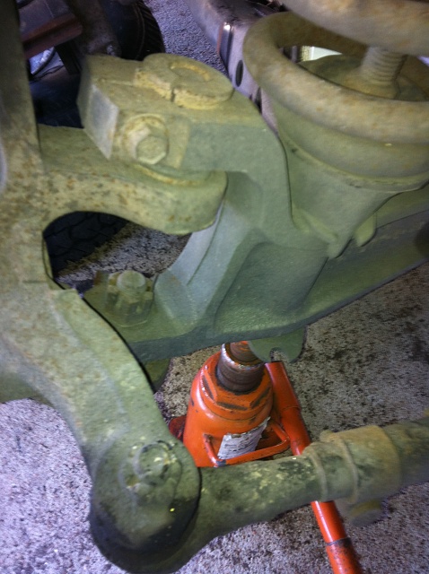 |
| F150 simular design |
http://www.realfixesrealfast.com/realfixesrealfast.com/Steering_%26_Suspension/Pages/Ford_F150_Ball_Joint.html
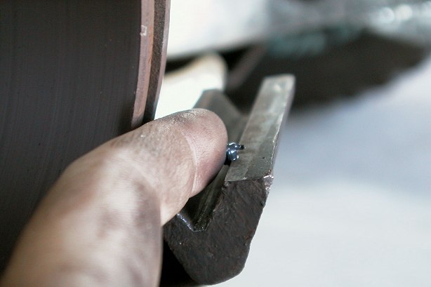
2. Using a clamp, remove the pressure the brake pads exert on the rotor. Remove the brake caliper and tie/support it.
3. Remove the tie rod end from the spindle. Do not take the nut completely off, this will protect the threads (from hammer blows) should you reuse it. Use a hammer hitting the ring. Put the nut on the tie rod end before you lose it. Don't reuse any cotter pin.
4. Take the cotter pin and nut off the lower ball joint. If the cotter pin is stuck, break off the "legs" by wiggling them in their hole. Soak with penatrating oil like PB Blaster. The nut size is a 24mm socket. Do not take the nut completely off, this will protect the threads (from hammer blows) should you reuse it and will prevent it from dropping off/out of the I-beam when the upper joint is free.
2. The upper ball joint is held in place with a pinch/clamp bolt. Clean away the rust and dirt out of the slot in the middle. Soak the shit out of it with penatrating oil like PB Blaster, then take that bolt out. NOTE: Tap the bolt with a hammer to help free it (don't over do this or you will mushroom the bolt head), some LIGHT heat may also be helpful.
 3. Your ranger has a camber adjuster (factory is preset) on the top of the I-beam to adjust the camber when the vehicle is aligned. It is trapped by the pinch bolt. Make a note where the camber adjuster was position, so that if it's adjustable you can put it back in the same place, or your alignment will be changed. You have to pry the adjuster out, soak with penatrating oil. Use a rod seperator or an open ended wrench to pry it up. Clean/polish it before reinsertion.
8. There isn't much holding the spindle in place now. You have to hit the bottom ring of the I-beam to free the lower ball joint. If you strike the eye with your hammer, it should break loose (see graphic).
9. When it releases, the heavy spindle will pop down, held in place by the nut. Remove the nut, remove the spindle.
TIP1: Check the brake line. If damaged, now is good time to replace it.
TIP2: Check all front end joints for replacement. These parts are fairly cheap online.
 1. Borrow the special ball joint press from the auto parts store ("C-frame assembly tool") to press the new ball joints in or out.
2. Remove any old grease fittings and rubber boots. The upper ball joint has a snap-ring on it. Spray the ball joint with the PB blaster both sides and the sanp ring. Hit the end of the end of the snap ring with a chisel or screwdriver to break it free from the rust, then used needle nosed pliers or a screwdriver to spread the snap ring enough to work it up out of the slot. Snap ring pliers also work.
3. The lower ball joint doesn't have a snap ring. It has a lip on the top of it (inside part of spindle) to keep the ball joint from going down through the hole. The lower ball joint can only be removed in one direction. The lower ball joint has to be pressed UP or tapped/beat up to remove it! Hit it with the PB blaster both sides. Prior to installing the replacement ball joints, clean the wheel spindel ball joint bores thoroughly, remove any burrs, grease bores with finger.

4. The upper ball joint should be installed first. Using the C-frame and ball joint installer, press the upper ball joint into place. Install a new snap ring into the groove at the bottom of the ball joint.
5. Using the C-frame and ball joint installer, press-in the lower ball joint.
6. And install the grease fittings. Install the wheel spindle. Grease the ball joints.

Thursday
2.3L engine pics
Often in the repair manuals their pictures would either suck or just never seem to show the one part, wiring, or location I needed to see. So here is a few that might help you.


 |
| Cleaned intake |
 |
| Old ignition module |


 |
| Crank sensor |

 |
| Test plug sprout |


 |
| Lower coil mount |


 |
| Spring detail |


Monday
Ignition Control Module R&R - 1991 Ranger
Tips you can use. This control module job can go great or poorly. Mine went poorly.

Outside of the fact that the unit is buried behind the alternator and not wrench friendly, my bolt heads were rusted beyond use. This would require the removal of the lower intake in order to to attempt the removal of the unit. Ultimately one bolt would snap, The other two bolts came out heat and oil, but only after breaking the unit off the bolts, so I could use vise grips on the bolts.
 TIP1: Heat is the enemy of the ignition control module.
Note there are only three bolts. The lower two are also grounds (verify the vehicle ground to manifold located at #4 cyl on manifold is good). Clean the backing plate well before installing a new unit. Note which plug is UP. Use anti seize compound on the bolts. Use heat compound or di-electric grease under the module required for heat transfer.
TIP2: Use a tap to clean the threads before installing bolts. If they break off during removal, you may need to remove the manifold.
TIP3: Remove the sensor from the manifold located in the tube to #1 cylinder. This is often choked with crap from the EGR system. Clean with a blast of carb cleaner and reuse.

Outside of the fact that the unit is buried behind the alternator and not wrench friendly, my bolt heads were rusted beyond use. This would require the removal of the lower intake in order to to attempt the removal of the unit. Ultimately one bolt would snap, The other two bolts came out heat and oil, but only after breaking the unit off the bolts, so I could use vise grips on the bolts.

Note there are only three bolts. The lower two are also grounds (verify the vehicle ground to manifold located at #4 cyl on manifold is good). Clean the backing plate well before installing a new unit. Note which plug is UP. Use anti seize compound on the bolts. Use heat compound or di-electric grease under the module required for heat transfer.
TIP2: Use a tap to clean the threads before installing bolts. If they break off during removal, you may need to remove the manifold.
TIP3: Remove the sensor from the manifold located in the tube to #1 cylinder. This is often choked with crap from the EGR system. Clean with a blast of carb cleaner and reuse.

Sunday
Coil Pack Pins
Identify the connector pins on the ignition coil assembly. If you look at the electrical connector you unplugged on the ignition coil assembly, you will see three small pins inside. The one in the center is B+.


Disconnect the spark plug wires from the ignition coils on the assembly by hand. The wires have a locking tab. To disconnect them squeeze the locking tabs inward at the terminal and twist the boot while pulling up. This also a good time to check the resistance of the spark plug wires and check for damage as you have them apart already.
Removing the coil pack and bench testing is best. Often there is cracking and damage on the underside of the unit which only can be seen if it is removed and cleaned.
Get a multimeter (digital is best) and set it to the correct range for ohm testing.
Checking the ignition coils' primary resistance. Probe pins B+ and coil 1 of the connector on the ignition coil assembly, and make a note of the number on the multimeter readout. Then probe pins B+ and coil 2. Make a note of each of your meter readouts. The resistance value for each pair of pins in your three tests should be between 0.3 and 1.0 ohms. If any of the coil packs (2 per unit) test out of this range (over or under), the pack should be replaced.
Check the ignition coils secondary resistance. Select the appropriate range in your multimeter so you can read between 6,500 and 11,500 ohms in the ohmmeter scale. Probe the two terminals on coil 1, where the spark plug wires 1 and 4 connect to, and make a note of your multimeter readout number. Probe the terminals on coil 2 and 3 and make a note of the results, as well. Any coil that tests outside of the 6,500 through 11,500 ohms range should be replaced. On 2.3L, 2.5L and 5.0L engines, if one coil pack is found to be defective, the other pack does not need to be replaced.
If any pack tested bad in either test, replace the unit.
The condenser usually mounted to the coil pack goes bad often creating a ignition miss, replace this item.
If the pack is good, reconnect the electrical plug, spark plug wires and the negative battery cable.
Other sensors that effect the timing are: MAP ( Manifold Absolute Pressure sensor ), IAT ( Intake Air Temperature sensor ), ECT ( Engine Coolant Temperature sensor ), EVP ( EGR Valve Position sensor ) and TPS ( Throttle Position Sensor ).

Fig. Fig. 2: Engine ignition coil harness connections-2.3L, 2.5L and 5.0L engines
Tuesday
Air Bypass Valve Info and testing
| Ford air bypass valve |
- cold engine fast idle
- no touch start
- dashpot
- over temperature idle boost
- engine idle load correction.
Symptoms of a bad one:
- Engine stalling
- Surging
- Poor idle conditions
- "Check engine light" on
Diagnosis:
The signal to the solenoid should be 1 volt or less at curb idle, (with all accessory loads off). Applying 12 volts to the solenoid will cause a neutral idle speed change greater than 1000 rpm. Check for shorts between both solenoid terminals and the case.
Codes 12, 13, 16, 17 & 19 all indicate idle speed is out of spec (too high or too low). Codes 47 and 48 indicate a fuel mixture problem which could be caused by an air leak. It may be possible to clean the ports with electrical safe clearer, do not use regular carb cleaner as it will remove the protective coating. Clean port holes in the manifold also before reinstalling.
Monday
Ranger brake proportional valve


Update: Ranger power loss, bogging, no acceleration
The catalytic converter was not the only problem. I decided before spending the money for a new cat, I would beat out the inside of the old one first. A tougher job than you might think. Took about hour or so and I need a heavy wire hook to remove metal packing and a pipe to break the inside up and a vacuum to suck the inside out also.
On the initial test drive, the problem returned and I wound up on the side of a busy highway. Once again finding no problem, I started back to the basics. I checked the fuel rail (for gas) using the schrader valve on the rail. The picture is not my truck, but this is what it looks like on the truck. Much to surprise it was full of air and not fuel.
I have not checked this out fully yet. More later.
Update:
Yes, low on gas was this problem. However, the power loss problem was still not solved. The short answer turned out to be a combination of several problems.
| Fuel rail schrader valve |
I have not checked this out fully yet. More later.
Update:
Yes, low on gas was this problem. However, the power loss problem was still not solved. The short answer turned out to be a combination of several problems.
 |
| Clogged sensor |
- The air sensor in the intake manifold was coated with goo. Cleaned and reinstalled.
- The ignition module was bad. See detail elsewhere on site.
- The inner air passage inside the intake to the EGR valve was blocked/choked. So bad it had no flow. Use a McDonalds straw to probe it on your truck. The straw (5/16) is just the right size, the tunnel is straight.
- The ground wire on the intake (needed for the ignition module) was weak. Replaced it.
- The intake was very very dirty. Cleaned it.
- Decided to replace the injectors with a set from a mustang 4 cly 2.3L. Mine were rusty and needed a cleaning. By the way, they work great.
- The blocked cat converter was "cleared" earlier.
 |
| Look at odd shape near center - Egr clogged vent |
Tuesday
Ford Distributorless Ignition System (DIS)
 |
| Ford DIS System |
Crankshaft timing sensor
DIS module
Two ignition coil packs
Spark angle portion of EEC-IV
Crankshaft Timing Sensor
The crankshaft timing sensor is a dual hall effect magnetic switch, which is actuated by the dual vane cup on the crankshaft pulley hub assembly. This sensor generates two separate signals, PIP (profile ignition pick-up) and CID (cylinder identification). The PIP signal provides base timing and RPM information, while the CID signal is used to synchronize the ignition coils. Initial timing (base timing) is set at 10 degrees BTDC and is not adjustable. Ignition Coil Packs
DIS Module

Failure Mode Effects Management
During some DIS system faults, the Failure Mode Effects Management (FMEM) portion of the DIS ignition module will maintain vehicle operation. If the DIS ignition module does not receive the SPOUT input, it will automatically turn the ignition coils on and off using the PIP signal. However, this will result in fixed spark timing (ten degrees BTDC) and a fixed dwell time (no CCD). If the DIS ignition module does not receive the CID input during engine cranking, random coil synchronization will be attempted by the module. Therefore, several start attempts (cycling the ignition from OFF to START) may be required to start the engine. If the DIS module loses CID input while engine is running, the module will remember the proper firing sequence and continue to fire to maintain engine operation.
Dual Plug Inhibit
Dual Plug Inhibit (DPI) is a function of the EEC-IV that is only used when the vehicle is being started at temperatures -7° C (20° F) and below. During engine cranking, the EEC-IV will only fire the spark plugs on the right hand side of the engine. When the engine has started, the EEC-IV will send a signal to the DIS module to start normal dual plug operation.
Ignition Diagnostic Monitor
The Ignition Diagnostic Monitor (IDM) is a function of the DIS module. The DIS module sends information on system failures to the EEC-IV which stores the information for diagnostic self test. The IDM signal also is used to drive the vehicle instrument tachometer, and test tachometer for system.
Testing
You can find a good DIS testing procedure using a breakout box HERE. The factory pinpoint test mentions using a breakout box (BOB). You can do the same test without a breakout box. The BOB just lets you connect to each wire non-intrusively. Without the BOB, you have to locate each wire and probe directly into the wire. The pinpoint tests refer to overlays and test harnesses, just read over the test first and get an idea what the test is checking, and then you can do the test without using the BOB and associated equipment.
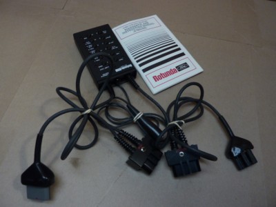 |
| DIS Break out box |
Subscribe to:
Posts (Atom)